
Burns Orbit Three


Dimensions:
21"h x 25"w x 10"d
Weight approx 37Ib
Advertised output power: 60watts (peak)

There are four different versions of this unit:
881 : 'Orbit Three' 3 x 10"
882 : 'Orbit Three' 3 x 10" with reverb
885 : 'Orbit Three Double 12' 2 x 12"
886 : 'Orbit Three Double 12' 2 x 12" with reverb
Burns quoted peak power for the Orbit Three. For testing purposes, with a continuous sine wave, expect just over 30watts rms at clipping into 2ohms.

Thanks to Jon at blackguitars.com for the 1963 advert clip.

NB: The Orbit Three Double 12 is not the same thing as an Orbit Double 12
881 / 885. Orbit Three Standard

882 / 886. Orbit Three Reverb "with extra dimensional control" if you're into that sort of thing.

Burns used a number of different circuits in Orbits, so it's pot luck whether the schematics apply. Problems finding replacement parts and service information (and the rats nest wiring) have probably contributed to the number that have been abandoned or broken up for spares. The recent obsession with stripping out the ELAC speakers and advertising them for hundreds of pounds each will probably see off many more that could have been saved. That's a shame, because they're interesting things when they work.
The unit used for the details below was a 3 x 10" that had been thrown down the stairs, buggered about with and stripped. To say 'beyond economic repair' would be to say that Ming The Merciless was a bit naughty but, luckily, it still had enough of the original components to work out the circuit and layout,
Don't be put off if the drawings don't match exactly. It should be possible to pick enough information from different versions to get the job done. Expect to find melted sleeving and back to front electrolytics from the factory, as well as multiple dry joints and fifty years worth of abuse. The resistance wire in the output device emitter circuits really doesn't like solder either and is a chief suspect if one half the output signal is distorted or missing. And yes, after trying some others, the tone selector switches all feel like they're about to fall apart.
Layouts below are viewed looking into the back of the pots with the power supply on the left. Everything is hard wired in and stapled to the woodwork. If the cabinet is laid face down though, there's just room to lift the chassis out and lay it across the back. Protect the back of the speakers from the heatsinks.


IMPORTANT: These drawings and notes are provided for interest only and are not guaranteed to be accurate. Use at your own risk and discretion. The equipment shown contains lethal voltages and should only be worked on by people with suitable training and experience. Schematics and layouts are typical but will vary.
PRINTING
Wix (bless 'em 😖) have changed their image format - again - to avif just to make them awkward to print. Unless you want to buy a converter, the easiest way to make a hard copy is:
-
Left click when the magnifying glass icon appears and wait for the picture to clear.
(On a touch screen, tap on the image). This will display a higher res file. -
Right click and 'save image as' to somewhere as an avif file.
(On a touch screen, touch and hold down to view the menu) -
Upload the saved file to your Google Drive.
-
Open the file and use the print menu to make a hard copy or save as a pdf.
Burns Orbit Three Schematics.
There are a number of different versions of the circuit, the main changes being around the tone circuit in channel 1. No idea what order they came in date wise, and so they're set out as Options 1, 2, 3 ... etc.
OPTION 1
Taken from a drawing marked BE 009 03, dated Sept 64, found on the internet. The 1amp fuse seems to have been added to the schematic later and is probably fine for instrument use. It's a useful mod if your poking about in the chassis; a new set of transistors is very expensive.

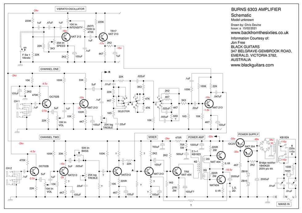
OPTION 2
The "6303" Schematic
Thank you to Jon Free at Black Guitars in Australia for posting photos of some back panels with factory schematic stickers. They're described as a 6303 Amplifier. We weren't sure which model they came from, but I just found the same tone circuit in the 3x10" Orbit Three below with CCL capacitors from 1965 (no serial number, unfortunately). Some of the values are unclear, but the circuit for Channel One in particular is a lot different to the BE 009 03 version.
Jon's site's got some very interesting Burns archives. Well worth a look.
BLACK GUITARS
347 BELGRAVE-GEMBROOK ROAD, EMERALD, VICTORIA 3782, AUSTRALIA
OPTION 3
As found in a Type 882, 3 x 10" built in or after 1965.
The details and layouts come from the wreckage of a real amp and you can see straight away that the wiring around the mains voltage selector switch is different (and still @#!!£* dangerous if you don't pay attention).
There's no fuse and it's ridiculously easy to flick over to 115V by mistake. Whoever built them also managed to find three core mains wire with two browns and a green. It's just pot luck which wire's the line.
NB: The layout drawings are specific to this chassis and this schematic.

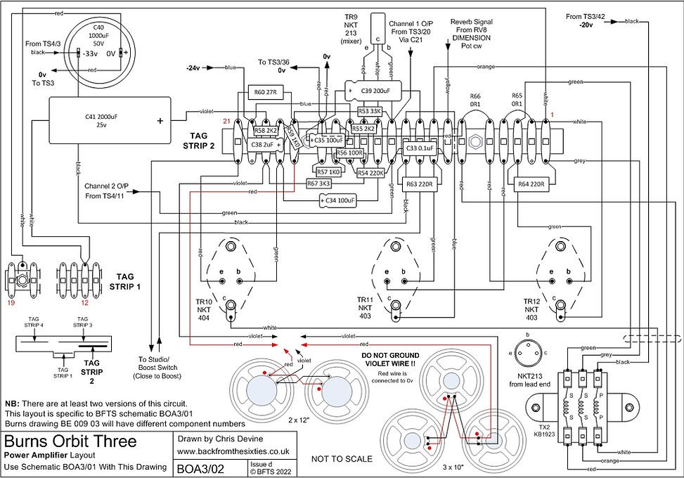
Burns Orbit Three. Power Supply Layout As Found

Burns Orbit Three. Power Amplifier Layout As Found.
Burns Orbit Three. Channel One Layout As Found.

Burns Orbit Three. Channel Two Layout As Found.

Burns Orbit Three. Vibrato Section Layout As Found.

Burns Orbit Three. Reverb Section Layout As Found.
Note correction in -20v supply in issue c.

OPTION 4
Yet another variation from a 3 x10" serial number 262. This is Channel 2.
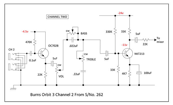
The rest of the circuit to follow.
Reverb Tank
A big thankyou to Colin Neville for dropping over another complete amp that's got all the original parts. More about that when I get a minute.
These are the details of the tank found in it. It's an old Hammond (or Gibbs) type 4, two spring unit with an ink stamped "C" on the inside next to the input connector and "6250" on the outside. There are no phono (RCA) plugs fitted to the cables (there isn't room).
Both connectors are grounded as supplied but there is an internal Burns mod that isolates the input signal from the chassis. The wiring is pushed through the suspension holes in the case and soldered internally..
The input side was open circuit, but it was just down to the ancient tinsel wires (both of them) joining the coil to the phono socket.
The table below shows what was fitted originally:
This is an extract from the Belton (Accutronics) web site at:
It's a good starting point but out of date. A new Accutronics type F, for instance, measures 248ohms at DC.

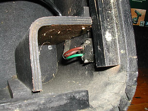
Replacements
Accutronics still do a tank that matches the old spec and still fits the existing screw holes on the back panel. Versions with isolated inputs and grounded outputs ####C## are quite difficult to buy in the UK but a ####A## is available from Hot Rox at www.hotroxuk.com/ . Part number is 4FB2A1C. I've just fitted one and it's perfect as long as you do the ground lift mod.

It's a bit difficult to see from the photograph but:
-
Disconnect the wire from the ground side of the phono (RCA) connector.
-
Solder one part of a double tag strip (or the one out of the old tank) in it's place.
-
Reconnect the wire to the other, isolated tag.
This is a ######D not C but the whole thing is quite happy working 'connectors down'. It's easy to convert if you want to.
Just swap the positions of the suspension springs in the large mounting holes. Upper springs towards the centre and lower springs towards the outer ends of the case.
The travel limiting pins should then sit in the centre of the big circular cutouts in the internal chassis. That's the only difference between the two types.
Speakers
The Orbital speakers in the 3 x 10" versions are Elac 10/N83s with a nominal 6ohm impedance.
Replacements aren't straightforward because of the limited space. Most modern speakers have a much deeper basket design that collides with the heatsinks in the upper two positions.
If only one unit has gone, it's possible to move things around and fit the new one at the bottom where there's plenty of room.
A usable alternative driver is an 8ohm Jensen C10R. The slightly higher impedance makes no audible difference. It still won't fit in the top positions though.

Foot Switch
The foot switch is a marvellous thing carved from a solid block of wood.
The switches aren't really designed for small signals but they respond well to a squirt of switch cleaner down the ends of the terminals.

