
Watkins Copicat MkII

IMPORTANT: These drawings and notes are provided for interest only and are not guaranteed to be accurate. Use at your own risk and discretion. The equipment shown contains lethal voltages and should only be worked on by people with suitable training and experience. Schematics and layouts are typical but will vary.
PRINTING
Wix (bless 'em 😖) have changed their image format - again - to avif just to make them awkward to print. Unless you want to buy a converter, the easiest way to make a hard copy is:
-
Left click when the magnifying glass icon appears and wait for the picture to clear.
(On a touch screen, tap on the image). This will display a higher res file. -
Right click and 'save image as' to somewhere as an avif file.
(On a touch screen, touch and hold down to view the menu) -
Upload the saved file to your Google Drive.
-
Open the file and use the print menu to make a hard copy or save as a pdf.
1) First of all, a big Thank You to Charlie Watkins for coming up with the echo unit that shaped the sound of so many bands over the years. The Copicat, in it's various forms, has never tried to compete in complexity with it's more expensive competitors like the Echoplex or Binson. Instead it remained an affordable, workmanlike tool that did the job it was designed for. For an expert run down on it's history and workings, and for spare parts, there's only one place to go, John Beer's excellent web site at http://www.amp-fix.com
Unfortunately John has semi-retired from repair work these days but still supplies parts. He's also now the only licenced supplier (and builder) of the Watkins Dominator reissue. All hand built, it's a beautiful thing to look at and listen to.
As for Copicats, the hardest to come by these days are the valve (tube) versions. As a lad I had a blue panel one in a light blue/cream case. Isn't it marvelous what you can afford when you still live with your parents.
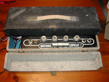
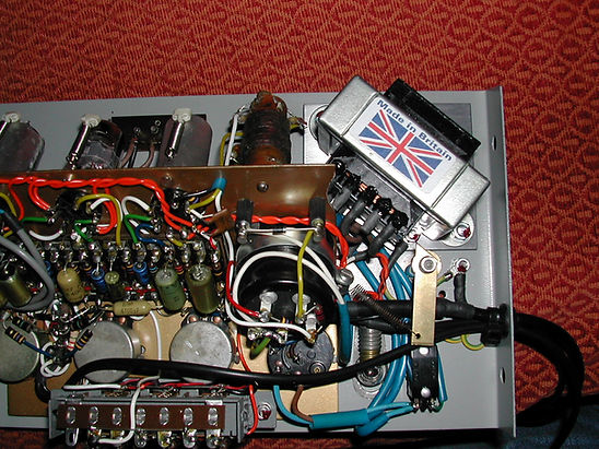
The unit in this case is a valved MkII with a black panel and cream case. The logo is Watkins rather than the later WEM and the components are mounted on a tag board. I sent John some pictures and he wasn't impressed.
'Good luck restoring that one, I don't think I would bother to be honest'.
Good advice. I should have taken it.
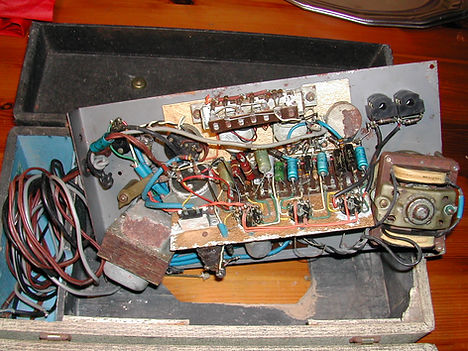
2) The starting point for this job is to assume that the thing is scrap. There just isn't enough good stuff left among the rust to salvage, so it's document and complete rebuild time.


3) First job; take everything off the metalwork. There are two sections, the front panel and a sub chassis which holds the valves and tag board.
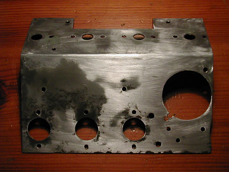

The sub chassis was rubbed down and filled with Plastic Padding Super Steel. This stuff has lasted ten years on an aluminium V8 engine block. That's more than you can say for the rest of the vehicle (mind you, it is a Land Rover).
After flatting with wet & dry, it was sprayed with red oxide primer and metallic gold cellulose (Nissan Gold).
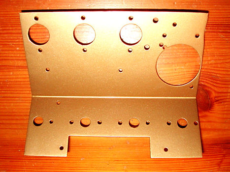
Brush painting with gold Hammerite didn't give a decent finish but you might have more luck spraying it on. Before painting, the large hole for the power supply cap was enlarged and redrilled to take a modern replacement.
4) The original power supply can was a three section 20/20/20uF by Hunts and it was very rusty. It's a waste of time putting another old one back in, so this is a new JJ 40/20/20/20uF. It's wired as a 40/20/20 with the unused section linked to ground. The JJ and it's mounting clip are fractionally bigger than the Hunts, hence the rework on the chassis.

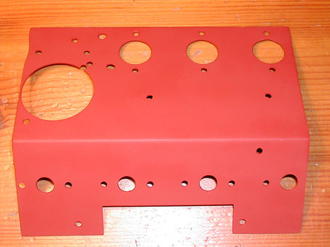
5) The front panel was easier. The back was rubbed down to bare metal and sprayed with red oxide and grey cellulose. The paxolin fuse holder/voltage selector is riveted in so It was just masked off.
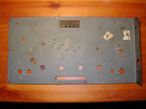

The front of the panel has been left as found for the moment. The cost of making up a new screen print for it would be out of all proportion to the value.
6) The tag board is insulated from the chassis by a strip of flexible material similar to old Fender eyelet boards. Both the board and insulator have been replaced. The insulator is now a sheet of thin paxolin.

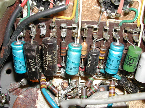
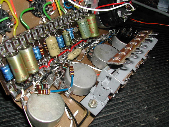
7) There's not a lot of room when the board is screwed to the chassis so the wires were attached first.
Resistors are new carbon composition and non electrolytics are NOS.
The old rectifier is going to be replaced with a 1N4007 mounted on standoffs. I probably needs an additional series resistor to compensate for the lower diode voltage drop.


8) Mains Wiring Layout
The mains wiring on this thing needs a bit of thought. The system, as it stands, relies on the output lead to the amplifier for a ground connection as there's no dedicated ground wire in the mains lead. That hasn't been too much of a problem in the past and there are still thousands of happy Watkins users alive and kicking. However, some entertainment venues, particularly those run by local Councils, have started asking in advance for PAT (Portable Appliance Test) certificates for all electrical equipment taken into the building. That includes the band's gear. No certificates, no gig. (Never come across anywhere that can be bothered to actually check them though)
For more details go to http://www.pat-testing.info/
They're not being awkward (no, hang on, this is the Council so they probably are). Penalties under EU health and safety legislation can be quite severe if employees or the general public are put at risk. (Edit: Getting electrocuted by your amp isn't a bundle of fun either). A PAT certificate isn't a legal requirement, but it's one way of showing that the kit has been properly inspected. Testing isn't expensive. There are companies that will come out and test all the average band's gear for about £50 (edit: that was a while ago :) Probably more like £150 now). Ask them to bring some sort proof of competence (City & Guilds Certificate preferably). It's very important to get ALL the gear checked. Having really good ground connections on the back line will guarantee sudden death if the PA system's faulty.

There are three parts to the test.
-
The mains lead is checked for correct wiring, fuse rating and physical condition.
-
The resistance of the Earth connection from the mains plug to any exposed metalwork is measured using a heavy current (typically 8amps AC with old testers) to simulate a fault. Modern test equipment uses a much lower current to avoid damage to computer based equipment.
-
The Live and Neutral terminals of the mains plug are shorted together and 500volts applied between these and the Earth terminal. The leakage current through the equipment is then measured.
Results need to be within limits applicable to the type of equipment under test.
PAT testing (or PA Testing if you want to be a bl###y pedant) doesn't actually involve taking the unit apart, so you can see that it isn't a substitute for a proper service. There's nothing to say exactly how often a full test should be carried out, but once a year (or more often if it gets very heavy use) is generally accepted. Between times, a quick visual check each time the kit's used is good enough.

I'm a paragraph. Click here to add your own text and edit me. It's easy.
The problem with old Copicats is that they don't come under any of the modern test classes. They're really Class 0, an unearthed metal appliance with a two core cable, illegal since about 1975.
If you look at the 1979 factory schematic No.577 of the much later IC300, it shows an earth connection. However, I've got an IC300 that doesn't have one, so the problem obviously exists in a large number of units. You can see more IC300 details here on another site page.
To make this one safe and testable all we really need to do is fit a new 3 core mains cable and earth the exposed metalwork. The motor might need hard wiring to the case if it's insulated by rust or paint (the spindle sticks up through the front panel). It should then fall into the Class 1 category.
That may bring on the old problem of hum caused by an earth loop. (It wasn't an issue in the end).
9) The head selector switch was in a dire state. The only option was to take it completely apart. This is guaranteed to break something.
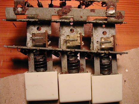

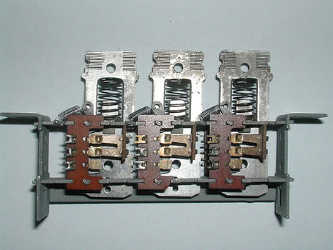
10) Progress to date.
Head selector switch back together. Replacements for the very small springs on the selector switch are available at Brocotts store on ebay.
Type - Expansion / Tension Springs
Length - 8mm (includes the end loop eyelet)
OD - 3.2mm
Profile - 0.2mm
Material - Passivated & Corrosion Resistant

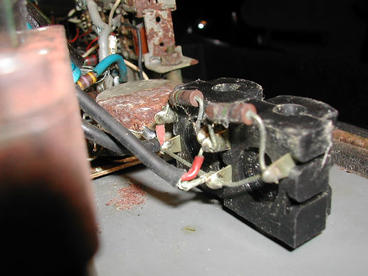
RIGHT:
The inside of the voltage selector fuse link. Warm up the plastic with a hair dryer before levering it out.
The fuse measures about 6x12mm but it was probably spec'ed as 1/4" x 7/16". Anybody know where you can get some?
It's rated at 1amp and looks like a quick blow (F) type. Optionally, a 20mm fuse can be soldered across the holder underneath the front panel.
LEFT:
The supporting metalwork cleaned up and coated with cold galvanising spray paint.

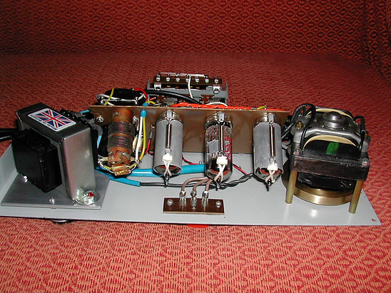
11) Why doesn't it fit?
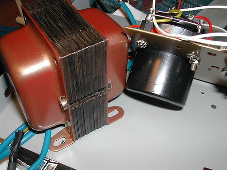

You can see why the edge of the sub-chassis has corroded away; this transformer doesn't fit the holes in the front panel. It seems to be factory original, so perhaps they were using up the old metalwork or an odd batch of transformers. That could also explain why there were only two screws holding it in. There are no signs that the other two have ever been fitted.
This set up seems to be common on black and white versions with "Watkins" logos, the proper four screw arrangement appearing on black and white "WEM" units (third picture below). The transformer painting's not finished yet.


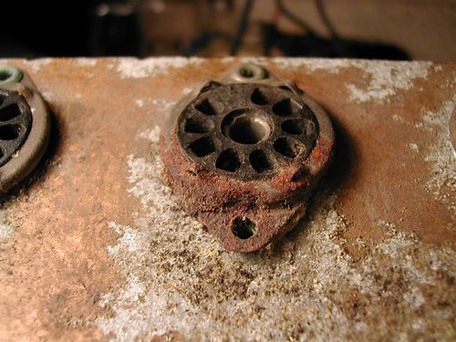
12) Head wear.


Three of the heads are original Marriotts and they're beyond help. What look like a fairly solid pieces of metal either side of the head gap are actually thin foil and regrinding (lapping) isn't possible. On the Brainiac principle of "We do it so that you don't have to", this is what happens if you try. New heads all round then.
Just out of interest, these are the measurements taken from some old heads.
Head A (Original Marriott playback head from a MkII valve unit) 413ohms, 464mH
Head B (Original Marriott playback head from a MkII valve unit) 420ohms, 455mH
Head C (Unknown manufacturer taken from an IC300 solid state unit) 69ohms, 106mH
Head D (Unknown manufacturer. Erase head taken from IC300 solid state) 26ohms, 1.66mH
Measurements were done on a Marconi LCR bridge,
resistance at dc and inductance at 1kHz.
13) Tension arm.
The tape tensioning arm looks innocent enough from above, but there's a lot hiding underneath it. At first sight the inserts in the wheels look like impregnated phosphor-bronze, but the colour isn't quite right and they could just be brass running on steel shafts.
The magnet was jammed in with a length of hook-up wire sleeving. The poles were at an odd angle so that was probably a DIY job after it fell out.
If you ever get your Copicat stripped down this far you might as well replace the magnet and tension spring while your at it. Both are available from http://www.amp-fix.com/ for just a few pounds (along with just about any other Copicat spare you could think of ). Adjust the new magnet so that it's close to the tape but not actually touching it, with the slot between the poles going from top to bottom.
If the magnet's missing just check that you haven't got a later version fitted with an erase head but still using an old style arm.

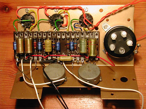
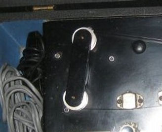
14) Here's the front panel on the way back to life.

The motor has been stripped down, treated with Kurust, cleaned and lightly lubricated with sewing machine oil.
It runs extremely quietly at the correct speed, but it gets quite hot. (Edit: This is not normal. See Section 26 below).
The motor is from Garrard, the record deck people, and features an extended drive shaft and brass flywheel.
Blue sleeves on the transformer hide the joints where the wires have been replaced. After forty odd years the old ones had seen better days.
The weight of the rotor is taken on a single ball bearing in the bottom housing (at the top in this picture) and the shaft is kept central by top and bottom gimballed sleeve bearings. I don't think these were ever intended to be serviced and should really be described as "sealed for life". It says a lot for Garrard quality that so many of them are still going strong.
(Edit: Not this one unfortunately. See Section 26 below)
15) Thought it was going a bit too well.........
The new tag strip from TAD is too big. It collides with the switch assembly and it's got to come out again. ###### it !
More pics as soon as a proper tag strip turns up. It needs one for the top of the selector switch assembly as well.

16) Amp-fix to the rescue. Thanks John.
New tagboards in the post from Devon this morning.
Some of the joints are left unsoldered where the footswitch and output cables attach. They can get in the way so they're best left till last.
17) Switch assembly wired in.

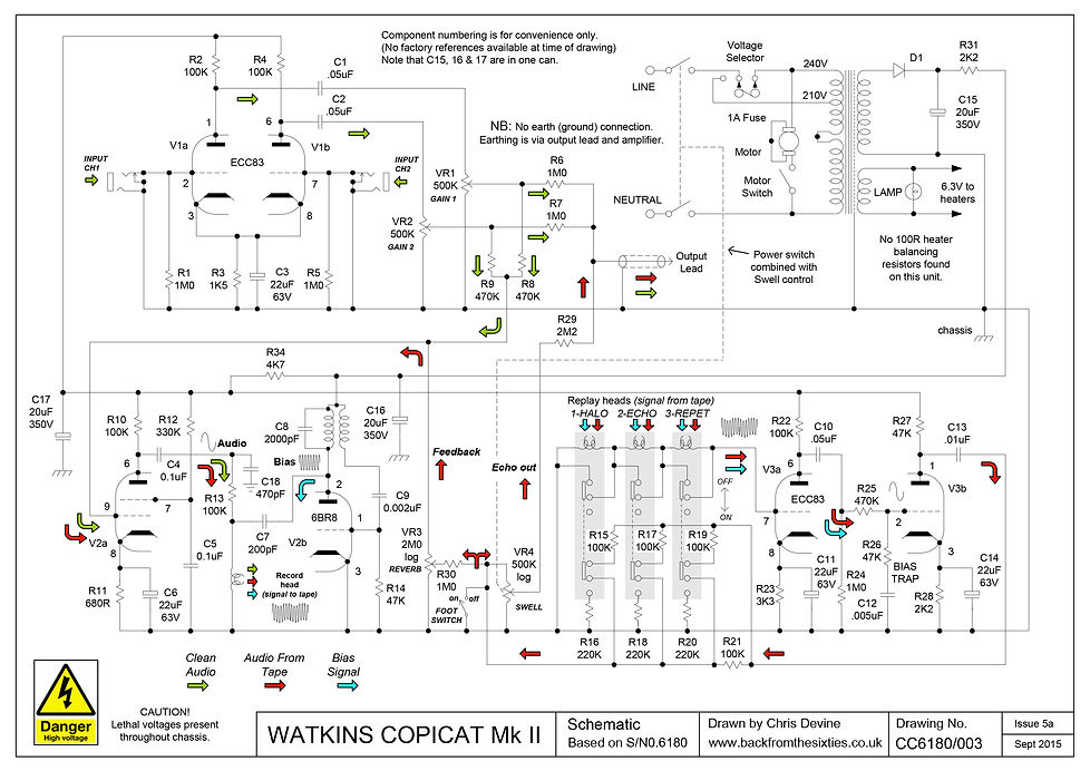
18) Watkins Copicat MkII Schematic.
This is an attempt to make sense of the head switching arrangement. Don't take these drawings as Gospel, there are probably a few variations out there. C10, shown on most schematics as .05uF, may be a .005uF in real life.
(Update 19/04/2015. In issue 3, R22 and R27 were on the wrong side of R34 (thanks again JB) )
Please read through the printing instructions above to get a clear download.
19) This is the tag board layout for the MkII.
Again, there are probably several versions of this layout in existance and yours may be slightly different. It's been known for the two halves of V3 to be swapped around.
Please read through the printing instructions above to get a clear download.

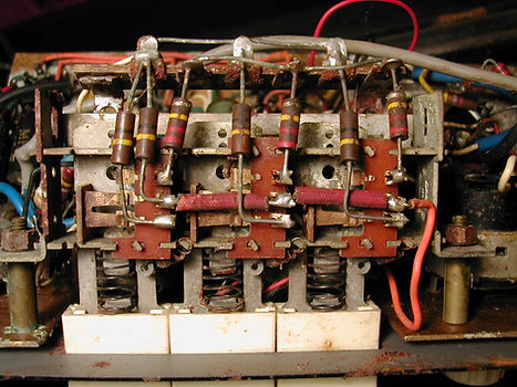
20) The Head Selector Switch Assembly
Notice that, on this particular machine, the 220K resistors R16, R18 and R20 find their way to ground through the metalwork and not a proper wired connection. It would be worth just doing a continuity check on this part of the circuit. Unselected heads are shorted when the switches are out (as shown).

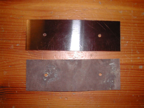
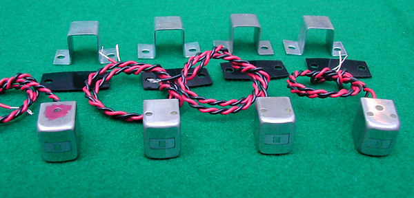
21) New Head Time
It's time to raid the bank and buy a new set of heads. The full replacement set, as supplied by Amp-Fix, is pictured below complete with brackets. The record head, on the left, is marked in red. They're a big investment, but it's not going to work without them.
RIGHT:
Heads and brackets trial fitted to the chassis (must clean up the screws). Although there are no instructions, everything is very straightforward and you can't go wrong if you replace and rewire one head at a time.
The heads need to sit very slightly forward of the brackets to allow the tape to wrap around them. They can be readjusted properly when the tape is fitted.


Life's a lot easier if you feed the wires through the panel before screwing everything down.
22) @#!!~# It
Just tried the mains transformer and one of the primary taps is open circuit.
( P.S. running out of ways to swear with symbols)
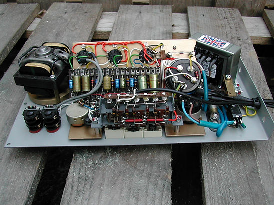
23) Cheer Up, it can only get worse.
Meanwhile, this is what the chassis looks like at the moment.

24) New transformer time.
Rather than mess about with the old transformer it's easier and cheaper to get a new one. This one is a VT1581CL (Edit June 2020: doesn't seem to be available any more). It's mounted on a 3mm aluminium sub-chassis to avoid changing the front panel holes. No complaints at all about the transformer or the supplier, but they might like to consider a new courier. APC Overnight combined a surly voice on the office phone with an extremely rude delivery driver. One to avoid.
A big plus point with the new unit is the option to re-link it for 120volts. The original only allowed 240v or 210v.
Spec is
Primary: 0 - 120 - 210 - 230 - 240V 50/60 Hz
HT Secondary: 230V @ 76 mA
Heater: 6.3V @ 1A
Dimensions: 68W x 55D x 58H mm
Fixing centres: 82 mm (95mm across feet)
Weight:1 kg
The transformer itself is nicely made, does the job and fits in the case. What more could you want?
LEFT:

A close up of the home made (sorry "custom built") transformer mounting plate and the earthing arrangements.
To make a proper connection, the paint has been scraped off the rear of the front panel around the bolt and the bottom nut has a shakeproof star washer under it. The bolt is in a new hole drilled in the front panel, but it could be fitted to the bent-up section near the mains lead. That would need a slot cut in the wooden case.
If anyone is worried about hum after fitting a proper, earthed (3 wire) mains cable, don't be. It made almost no difference.
Problem to be aware of: The footswitch may not fit in the case if the mains cable is too thick.
There are additional earth links going to the transformer mounting plate and to the common (0v) tag of the main electrolytics.
The common rail is already grounded at the tag board between VR1 and VR2, but the connection relies on the pot bushes to reach the front panel.
It's normal to ground the common rail as near to the inputs as possible, but the arrangement shown had no noticeable effect on the hum level and it's easier to wire.
25) Getting there.
It's "Thank you Amp Fix" time again.
Had a bit of a break from this one, but John Beer has done what he does best and come up with some impossible to replace parts. Most importantly the U nuts that clip over the case divider and hold down the left hand side of the chassis. The plywood is 1/4" thick here and new nuts that wide just don't exist. Screws are No8 x 5/8" (16mm) flanged self tappers.

Time to defrost the workshop and get the old girl back on stage.
26) More B####y Problems
Remember somebody mentioned a motor running hot up in section 14 ? Well it finally decided to quit with an open circuit winding.
Question: Where do you get a replacement motor for a fifty year old Copicat?
Answer: From a fifty year old record deck...obviously.
Charlie, in his infinite wisdom, used a standard Garrard induction motor with a long spindle. The motors were used in thousands of decks and they're still about. The problem is finding one with the four corner holes drilled out. This one came from ebay for £10 plus postage (thanks Les) and is from a 4SP deck. Other models that might be worth a look are 4HF, AT6 (might need rivets drilling out), RC98, RC120, RC121, RC210, RC211 and TA MkII.
The old favourite SP25 MkI and MkII might be OK, but MkIII and upwards have different motors.
Even if the new spindle is the right length, it's easiest to just swap over the rotor assemblies complete with fan and flywheel. Alternatively, it's possible to swap out the coils by knocking two locking pins out of the core.

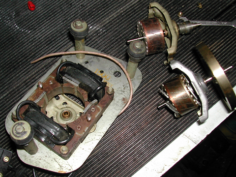
ABOVE left:
The motor assembly on it's original mounting. Remove two 4BA nuts and lift the rotor out.
ABOVE right:
The record deck rotor assembly (top right in the picture) with the Copicat version below it. The Watkins has cooling fans pressed on above and below the laminations but still fits into the cage. Add a small amount of light machine oil (not WD40 or grease) to the top and bottom bearings while they're accessible (Garrard used to recommend sewing machine oil). Too much on the top bearing will wick up the shaft and get splattered all over the flywheel.
RIGHT:
Back in the chassis and working nicely (when it's the right way up).
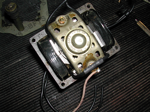
LEFT:
The original plastic contact block removed and the two windings connected in series for 240volt operation. The joint is insulated with glue-lined heat shrink sleeving (just above the pink ground wire).
If the rebuilt motor runs slowly, the polarity of one of the coils may need changing.
The pink wire isn't needed and can be removed.

27) Don't think there's anything left to fall off (famous last words). Meanwhile it's working well and sounding good. Just needs a period footswitch.