
Laney Supergroup 60

Not sure when these models officially became Supergroups, but that's what this case style is generally known as, so we'll stick with it.
Nice amps and generally very reliable. They're all over fifty years old now though and need looking after.

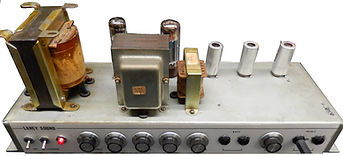
Date wise, this chassis has electrolytics from mid 69 and Mullard mustards from late 68. Best guess is late 69 into early 70s. The transformers predate the Partridge versions (I think).
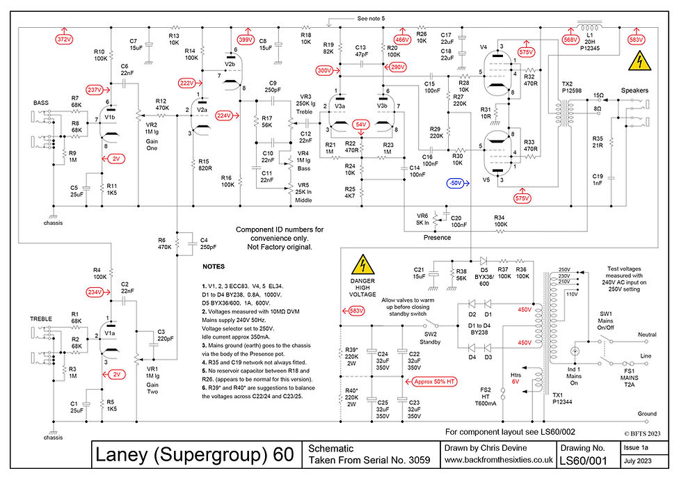
Mains voltage options are from a time when supplies still varied across the UK and the only options are 110, 210, 230 and 250V. Whatever Brussels says, the standard AC voltage in the UK is still 240V not 230, so we're no further forward. It's a matter of personal choice, but setting the selector to 250V is possibly the way to go given the very high DC voltages in the circuit. The voltages shown in the schematic were measured with a 240V supply and the selector set to 250V.

IMPORTANT: These drawings and notes are provided for interest only and are not guaranteed to be accurate. Use at your own risk and discretion. The equipment shown contains lethal voltages and should only be worked on by people with suitable training and experience. Schematics and layouts are typical but will vary.
PRINTING
Wix (bless 'em 😖) have changed their image format - again - to avif just to make them awkward to print. Unless you want to buy a converter, the easiest way to make a hard copy is:
-
Left click when the magnifying glass icon appears and wait for the picture to clear.
(On a touch screen, tap on the image). This will display a higher res file. -
Right click and 'save image as' to somewhere as an avif file.
(On a touch screen, touch and hold down to view the menu) -
Upload the saved file to your Google Drive.
-
Open the file and use the print menu to make a hard copy or save as a pdf.
Laney Supergroup 60 Schematic
An odd thing about the circuit is the apparent lack of a decoupling cap between R28 and R18. There wasn't one on this chassis and there was no sign of it ever having been there. It doesn't show up in photographs of other similar chassis either.
It's probably worth adding the resistor ladder R39 and R40 across the main electrolytics to even up the voltage share. There can be a really large imbalance as the caps start to age.
Laney Supergroup 60 Layout
The main ground connection to the chassis goes through the case of the Presence pot. Not the best idea in the world. The tabs holding the back of the pot onto the shaft are only folded over and they tend to corrode with time. It's also not possible to really tighten the pot down without risking damage to the front facia. Worth a look if there are problems with a PAT test.

