
Vox Conqueror
.. a look inside the Supreme's 30watt little brother


IMPORTANT: These drawings and notes are provided for interest only and are not guaranteed to be accurate. Use at your own risk and discretion. The equipment shown contains lethal voltages and should only be worked on by people with suitable training and experience. Schematics and layouts are typical but will vary.
1) First of all a big thank you to Trevor Dymott for letting me strip down his amplifier to document it.
The amp is actually in very good condition and much better than the photographs suggest. The control panel has dropped (probably in the post) because the two wood screws which locate it vertically are missing. This is very common and easily fixed. All it needs is a check up and some TLC to make it a very desirable amplifier. Trevor has the matching cabinet (minus the hoop stands), the original footswitch and a genuine replacement for the reverb channel selector knob.


From photographs of the cabinet, the speakers appear to be silver Celestions.
PRINTING
Wix (bless 'em 😖) have changed their image format - again - to avif just to make them awkward to print. Unless you want to buy a converter, the easiest way to make a hard copy is:
-
Left click when the magnifying glass icon appears and wait for the picture to clear.
(On a touch screen, tap on the image). This will display a higher res file. -
Right click and 'save image as' to somewhere as an avif file.
(On a touch screen, touch and hold down to view the menu) -
Upload the saved file to your Google Drive.
-
Open the file and use the print menu to make a hard copy or save as a pdf.
2) Power Amp Schematic.
Quick note..... These drawings were done in a hurry, so double-check your own circuit if your doing repairs.
This is the circuit as found. This amp is in remarkably good, original condition but, like anything of this age, it's been serviced in the past. There are therefore one or two caveats.
-
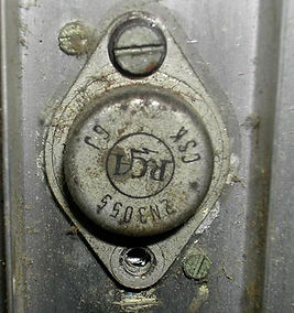
The output transistors are period RCA 2N3055s but they've been changed or refitted at some time.
-
The drive transistor has been scratched during previous service work and the markings are unclear. It's probably a 2N3054.
-
The 1K1 resistor in the drive transistor base circuit has been replaced so the value can't be confirmed. The Defiant and Supreme have the equivalent of 1K3 in this position so we're in the right ball park. Incidentally, this is the same resistor that was open circuit in the Supreme on this site and it would be a good place to start if you have a dead power section.
-
AC and DC voltages were as measured with 240V AC mains.
The most striking difference between this and the Defiant/Supreme versions is the lack of a second power supply for the drive transistor and pre-amp. These are supplied via a 10ohm resistor from the positive 38V line. The thermal cut-out hasn't appeared yet either.

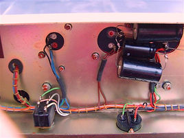
3) Power Amp Layout.
This is the area of the power amplifier below the chassis.
The only signs of re-work are a couple of new resistors and the extra caps across one of the electrolytics. The original is still in place and could fairly easily have a new capacitor hidden inside it.


Components in the drawings below are shown out of position to clarify the wiring.

The corresponding upper section.


4) Preamp Schematic (left click to enlarge)
This is a first try at an early (MkI ?) preamp schematic. The basic circuit was taken from this Conqueror and should be OK, but the component values on the cicuit boards are from a Supreme (didn't have the amp long enough to check everything). If you find any mistakes I'd appreciate a shout. Notice the difference in the MRB circuit between this and the MkIII on the Supreme page.
June 2020: Issue 4 has a correction to the MRB section.

5) Vox Conqueror, Defiant and Supreme Footswitch
The Conqueror shares a common three way effects footswitch with the Defiant and Supreme. Although the casting has a V for Vibrato, all the amplifiers panels are marked Tremolo.


6) Vox Conqueror Cabinet Dimensions
If the "Conqueror" badge and serial plate are missing, the Conqueror can be distinguished from the Defiant by it's size and single row of metal ventilation grills.
The front to back dimension of the larger Defiant is approximately 280mm and it accomodates two rows of grills. (Later, Vox Sound cabinets in this series all had a single row of plastic grills).

7) Switch On

There were a couple of mechanical problems. One 2N3055 only had one screw securing it and both were fitted with unnecessary mica insulating washers. The heatsinks on all of this Vox solid state range are insulated from the chassis and the output transistors should be mounted directly to the metalwork with a thin layer of heatsink compound.
It's obviously important to avoid shorting the heatsinks to the chassis or each other when the amp's out of the case.
The real problem was a broken output transistor socket. The solder tag (in the picture on the left) should be crimped onto the collector connection. It had fallen off and been held on (loosely) with an extra nut. Result - noise and occasional DC across the speakers.
The output transistors had been either swapped around or changed at some time and there was an unacceptable offset and very high quiescent current. After repairing the socket, a quick check of the power section showed everything to be working with a healthy 32watts rms output at clipping. The only thing needed then was to re-mount and re-bias the output transistors to cure the DC offset.
Free advice bit.....I know it's interesting to mess with them but the original bias adjusters are wire wound sliders and spares don't exist. They'll be locked with paint and very difficult to free off. So, If the amp's working and doing the job, LEAVE THEM ALONE.
Setting up the output stage isn't described here as it really requires a fully equipped workbench but, for anyone who takes the job on, aim for about 20mA quiescent and less than +/-20mV offset.
With the output transistors re-mounted and set up, this is a lovely little amp and, while it has any number of effects available, I think most people will find one particular sound that suits their style. Testing it with a 335, I preferred the Brilliant channel with the top boost and reverb on (that's exactly the same set up I used with my old Supreme and a Strat years ago - nothing changes does it).