The Redmere Soloist
Channel 1 Schematics and Layouts

IMPORTANT: These drawings and notes are provided for interest only and are not guaranteed to be accurate. Use at your own risk and discretion. The equipment shown contains lethal mains voltages and should only be worked on by people with suitable training and experience. Schematics and layouts are typical but will vary.
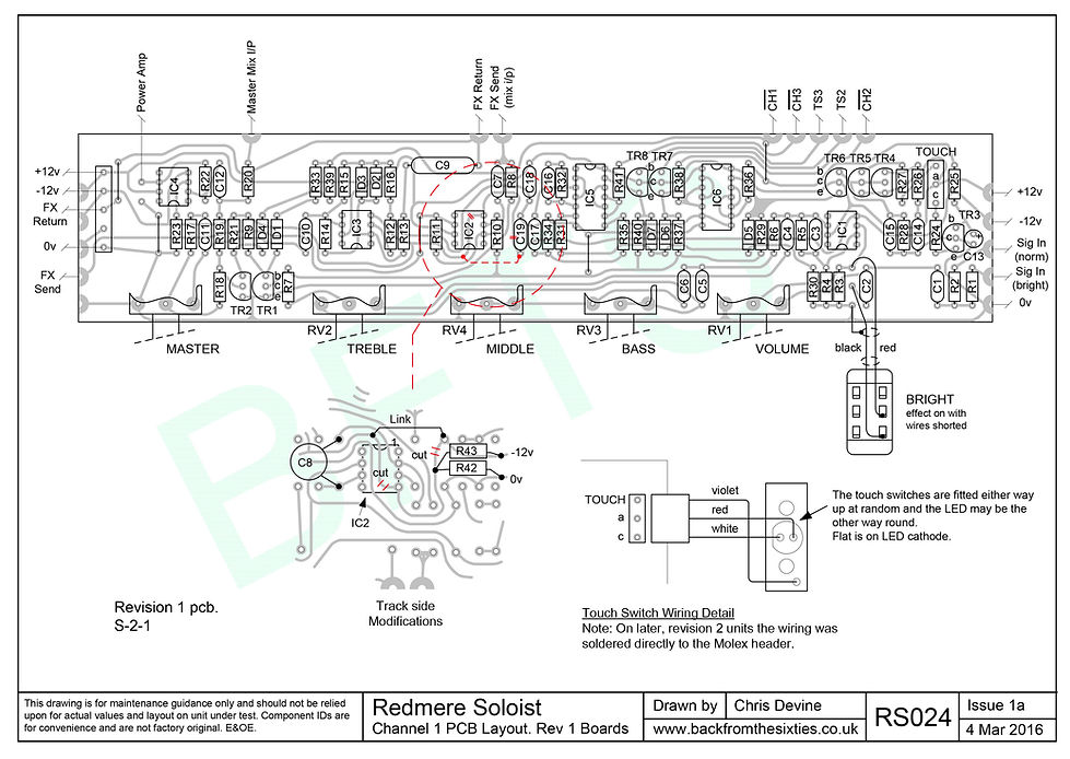
S-2-2 boards are re-laid to accommodate the track cuts on S-2-1. There is also a change in the connection of the 68pF capacitor (C8) around IC2.
Click the images to magnify.
PRINTING
Wix (bless 'em 😖) have changed their image format - again - to avif just to make them awkward to print. Unless you want to buy a converter, the easiest way to make a hard copy is:
-
Left click when the magnifying glass icon appears and wait for the picture to clear.
(On a touch screen, tap on the image). This will display a higher res file. -
Right click and 'save image as' to somewhere as an avif file.
(On a touch screen, touch and hold down to view the menu) -
Upload the saved file to your Google Drive.
-
Open the file and use the print menu to make a hard copy or save as a pdf.
Channel 1 Schematic. S-2-1 Boards

Channel 1 PCB Layout. S-2-1 Boards

Channel 1 Schematic. S-2-2 Boards

Channel 1 PCB Layout. S-2-2 Boards

